
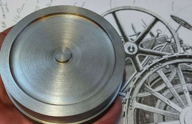
The Burrell engine flywheel at 1/20th scale is a tiny 72mm in diameter and just 9mm wide. I’ve machined this from a piece of solid extruded cast iron. Firstly turning the surface profile on the lathe.
Machining the Spokes
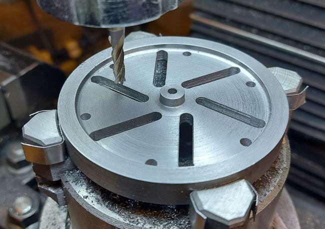
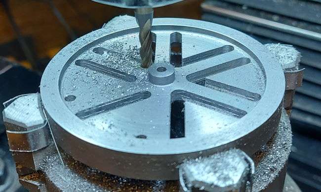
The process of machining a flywheel has been discussed before. Hence I will leave you with these images that hopefully take you through the steps I took in making this flywheel from solid. Also, I hope you like the illumination in the images with the angel eyes lighting, so much clearer to work with on the Sieg SX2.7.

Flywheel mounted on rotary table with dividing head. First slot machined one side of a spoke. Slots machined every 60°. Size of the flywheel in perspective. One set of slots one side of all spokes complete. Mill offset to other side of the spoke to machine second set of radial slots.


Roughed Out Burrell Engine Flywheel

The small 72mm flywheel after having been roughed out in cast iron. I now have the Burrell engine flywheel.
I just need to round the edges of the spokes. I’ve thought about tapering them as well, but how?

The flywheel laying on the 2x drawing of the flywheel. The issue as pointed out by an engineering colleague is that the rim looks rather deep. If you look at images of Burrell traction engines the flywheel rim is a thin band.
Now I need to think about how to machine and achieve this look at this scale in cast iron. I wish I had made this in mild steel. Might have been much easier and more robust to make it much thinner.
My other concern is the weight and more importantly the rotational inertia. Will it be enough for the engine? (See also flywheel design principles)
I’m going back to the lathe and milling machine to have a go at thinning down the rim and creating that more elegant look of a Burrell engine flywheel. Thin long spokes.