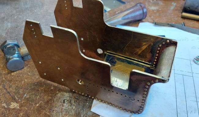
The 1/20th scale Burrell traction engine has moved on to the hornplates and tender body. In one of the last posts I cut out the hornplates+. The sides are from 1.6mm thick brass and the base and back are from 0.6mm thick brass. I folded the edges of the base and riveted them to the side plates.
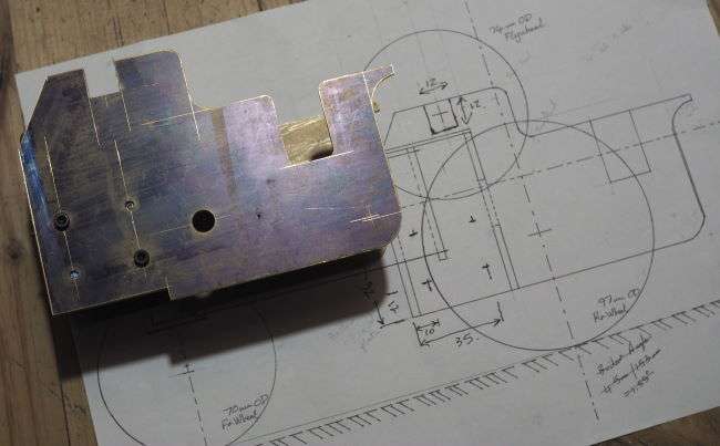
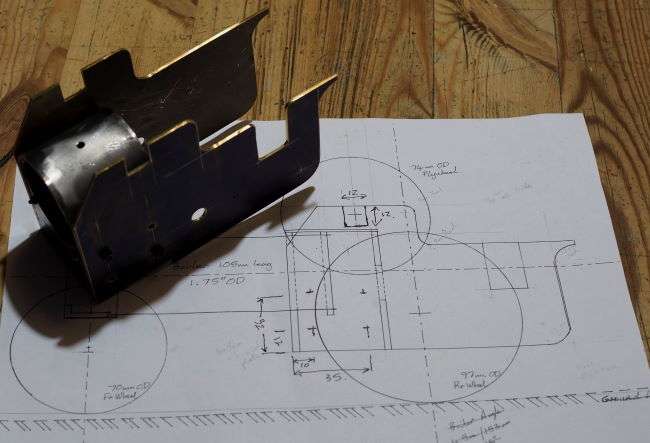

I also soldered the base to the sides to make the structure more stable.
The whole structure was heated using a hot air paint stripper. The 1600W of hot air distributed into the structure and I was able to then easily apply the solder along the edges.
Once the baseplate and rear of the tender structure were soldered and riveted the structure as a whole was quite rigid.

Cutout for the driver access is on the left hand side. The larger 8mm hole is for the main axle. 8 off M3 bolts fix the hornplates to the firebox. Holes for rivets for the upper bulkhead above the firebox were drilled whilst the plates were fixed together.
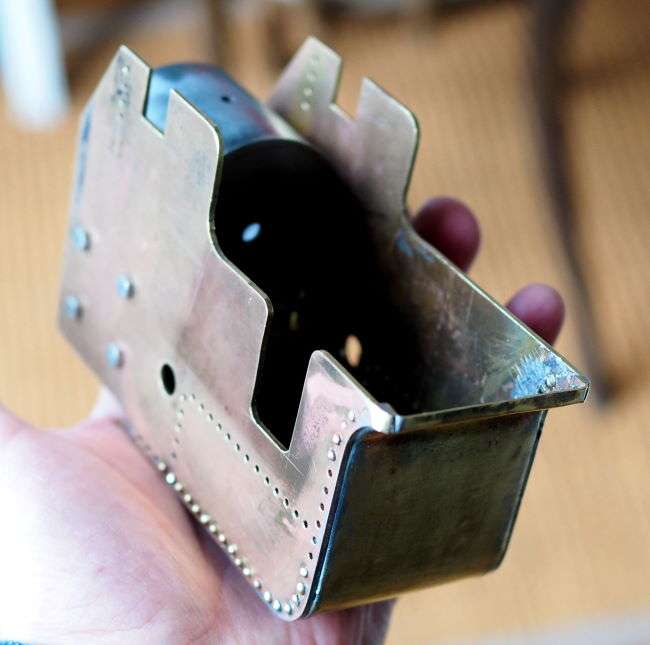
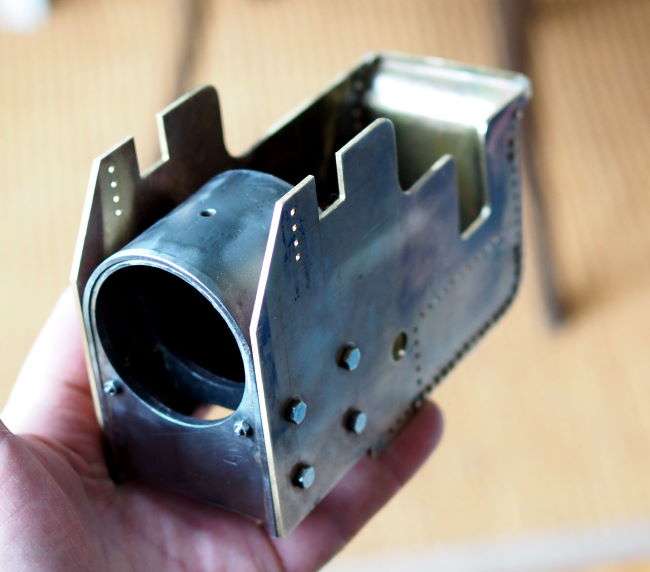
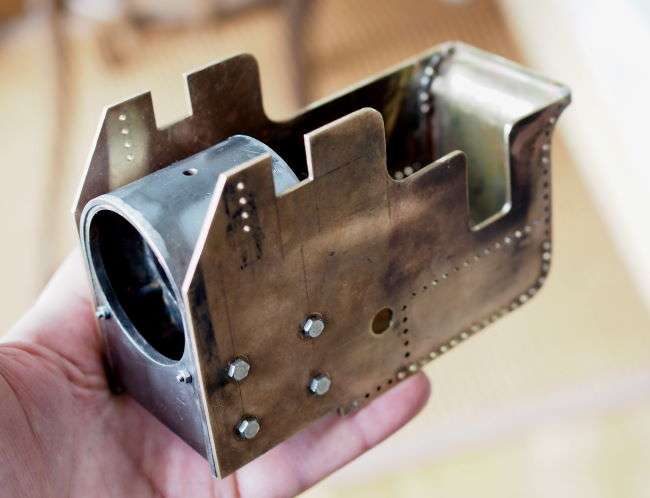
Eight M3 stainless steel bolts fix the hornplates to the firebox. There is a small amount of play, but once bolted up this adds to the overall rigidity.
Water Tank and Pump
I’m still wondering whether I include a working water tank. It would be great to have a pump so I can keep the boiler topped up. However, this feels like a lot to design and build into this quite small engine. Either way I need to fit a floor into the tender for the driver to stand on. This would also be the top of the water tank.
The two images below show the brass plate that forms a volume in the bottom rear of the tender. This again will be riveted and soldered. However, I just need to consider the water tank question as I will need to add a filler and access point for the pump.
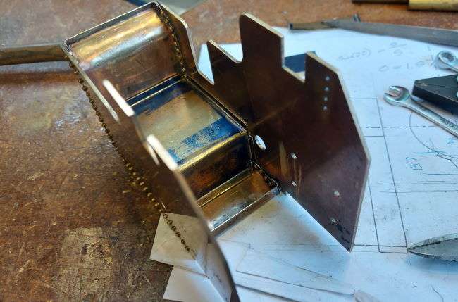
The water pump would need to be upright so that I could work it from a rear corner of the tender. This does mean though that I need to make a bespoke pump. It would mean that I think I can then run using coal and get the authentic look, smell etc.
The hornplates and tender body have a number of other features and fittings to complete. I think some time on the drawing board and research of different engines is required.