Electrically heating the boiler will allow me to correlate the mathematical model of the boiler. This will also allow me to explore boiler insulation techniques.

The instrumentation of the small vertical boiler has allowed me to establish the losses of the boiler and the heat output of the methylated spirit burner. This has then allowed me to optimise the design of the methylated spirit burner and the firebox.
However, a controlled electrical input will allow me to correlate these numbers as I will know more accurately how much heat I’m putting into the boiler.
Resistance Wire

I bought a reel of nichrome heating wire with the following specification:
- 0.5mm in diameter
- 7.5m long
- 0.551Ohm/m
- Withstands High Temperatures
- Corrosion Resistant
However, I cannot put this straight into water as I will generate gases from the potential difference and this could cause an explosion within the boiler.
I could make a heater like the immersion heater in the water tank at home. However, that means making up a miniature ceramic core to wrap the wire around.

The boiler was wrapped in a thin layer of Teflon. This Teflon sheet is available from cooking suppliers and is designed as non-stick baking sheet.
Big choc-block electrical connectors were used to connect larger electrical cables. I didn’t want these power supply cables to heat up. In hindsight I should have used these cables all the way to the power supply.
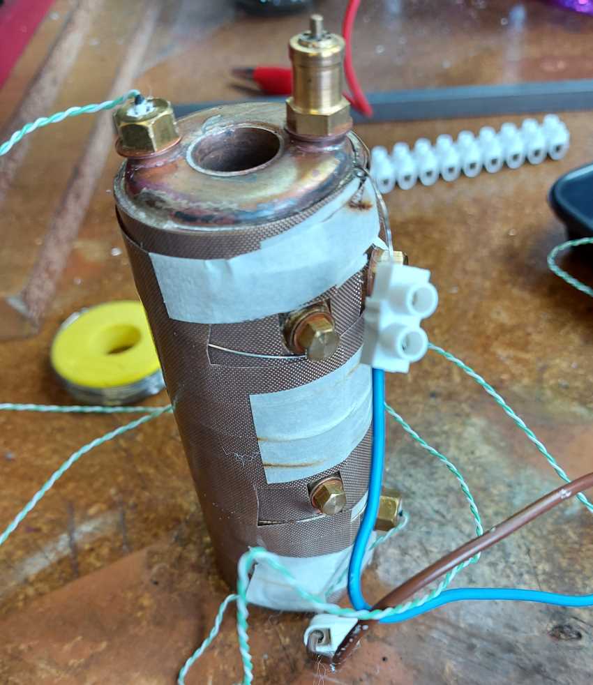
I then wrapped a second layer of Teflon sheet over the nichrome heating wire.
The masking tape did a reasonable job of holding the sheets in place for the duration of the experiments.
Note that the thermocouples were in place at this point. All of these cables had to be carefully wrapped in the next layers of insulation.
Electrical Power Supply

I used my benchtop power supply to drive the heating wire. This allows me to control the voltage and the current. However, depending on the electrical load the level of control can be limited.
The power supply and the nichrome wire was very stable at 10.7V and 1.89A with a very small variation over the length of any experiment.
10.7V x 1.89A = 20.2W
Measuring the voltage across the heating wire I see a drop of 0.3V in the supply cables and connects. Hence the heating power is
10.4V x 1.89A = 19.7W
This is not a huge amount of electrical heating, but it is good enough to get some data with which to calibrate the model.
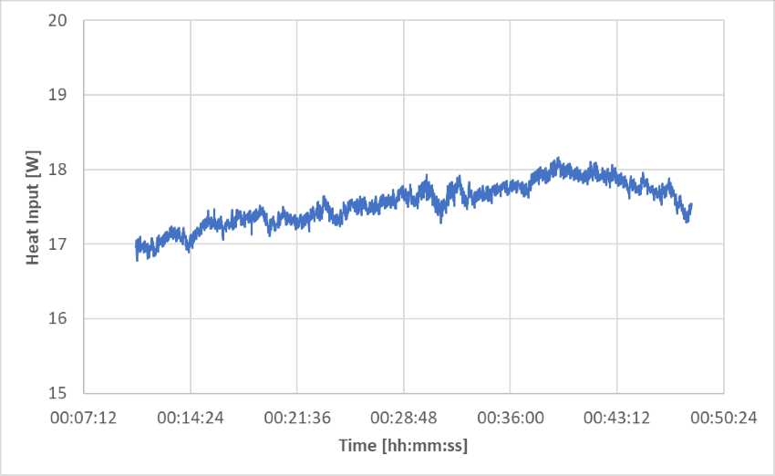
When I use the mathematical model I can estimate the heat input to the boiler.
Conclusion
Electrically heating the boiler with 20.2W of electrical power input results in between 17W and 18W of heat input to the boiler. This feels like a sensible result.
The efficiency of this electrical heating system is 100 x 17 / 19.7 = 86% which doesn’t feel bad for a first attempt.